Selecting a driver board for an insulated-gate bipolar transistor (IGBT) module requires more than matching a voltage rating. Compatibility depends on electrical characteristics, gate-drive requirements, protection functions, connectors, and mounting dimensions. For power-conversion equipment manufacturers, checking these factors early can prevent redesign, shorten validation, and improve serviceability. A board that fits physically but fails to match the module electrically can compromise switching performance and reliability.
Start With the Module Family and Electrical Ratings
The first compatibility check is the exact module family. IGBT modules can differ in package dimensions, terminal layouts, gate connections, and internal topology, even when their voltage and current ratings appear similar. Engineers should confirm the manufacturer’s part number and consult the module datasheet before selecting IGBT driver boards.
Voltage class is another consideration. The driver must provide suitable gate voltages and maintain appropriate isolation between control electronics and the power stage. The module’s recommended positive and negative gate voltages, gate charge, and switching characteristics should all be reviewed. Compatibility with one module family should not be assumed for another without documented confirmation.
Topology matters as well. A two-level converter has specific drive-channel and timing requirements. Confirming the circuit topology helps engineers determine whether the driver’s channel configuration matches the power stage.
Gate Voltage, Current, and Protection Compatibility
Gate-drive output determines how an IGBT transitions between its on and off states. The selected driver should match the module’s recommended gate-voltage ranges and provide sufficient peak gate current. Inadequate drive capability can increase switching losses, while overly aggressive switching may contribute to voltage overshoot and electromagnetic interference.
Protection features must also suit the application. Functions such as undervoltage lockout (UVLO), Miller clamping, and short-circuit-related protection help manage switching conditions and faults. Engineers should verify how fault detection, shutdown, and feedback work and ensure the control system can interpret fault signals correctly. The exact protection functions must be confirmed in product documentation.
Thermal conditions also affect driver capability. Output-power ratings may be specified at a defined ambient temperature, so engineers should check the stated conditions rather than treating a maximum value as unconditional.
Mechanical Fit: Dimensions, Connectors, and Mounting
Electrical compatibility does not guarantee a straightforward installation. Before approving a driver board for IGBT module integration, engineers should compare board dimensions, mounting-hole positions, connector orientation, clearances, and gate and emitter connection locations. Small differences can interfere with enclosure walls, busbars, cooling hardware, or adjacent components.
The electrical interface deserves particular attention. Connector type, pin assignment, polarity, and signal definitions must match the module and control system. A connector that appears to fit does not prove pinout compatibility. Teams should also review creepage and clearance requirements, insulation barriers, and control-signal routing against applicable design standards.
Maintenance matters, too. Access to connectors, fasteners, and test points affects how easily technicians can replace a board or troubleshoot a system. Clear documentation and repeatable installation procedures are valuable for OEMs manufacturing equipment across multiple production runs.
Evaluating Firstack’s 2FHD0225 Driver Series
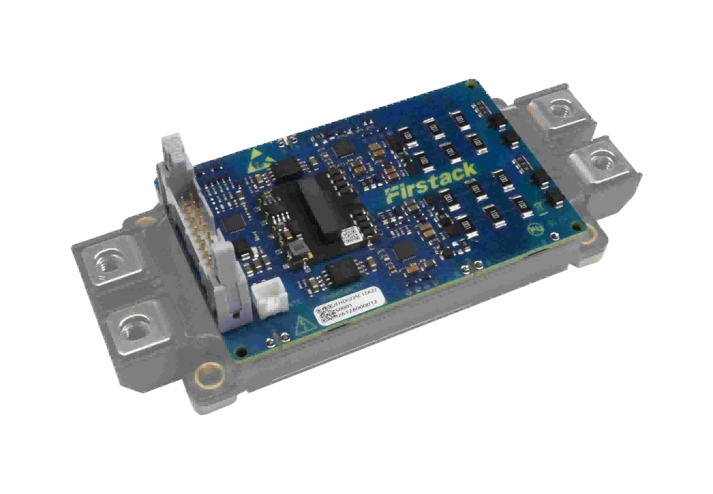
Firstack’s 2FHD0225 series comprises dual-channel, plug-and-play gate drivers developed for EconoDUAL™ IGBT modules with voltage ratings up to 1700 V. The series uses a two-level topology and provides up to 2 W output power per channel at maximum ambient temperature, with a peak gate current of 25 A.
Its specified positive gate-voltage range is 15–20.5 V, while the negative gate-voltage range is -9.5 to -0.5 V. The operating ambient temperature range is -40°C to 85°C. Integrated functions include soft shutdown (SSD), undervoltage lockout (UVLO), and Miller clamping. Distributed NTC sampling is also specified for temperature-sensing arrangements within the intended system design.
These specifications provide a starting point for evaluating IGBT driver boards, but they do not replace a mechanical fit check. Engineers should confirm the exact EconoDUAL™ module variant, interface and pinout, mounting arrangement, required gate voltages, and thermal conditions. Current product documentation should be consulted for complete electrical and mechanical specifications.
Validate Compatibility Before Production
A disciplined review combines datasheet comparison, mechanical inspection, and functional testing. First, record the exact module and driver part numbers and compare their documented interfaces. Next, verify mounting and clearance in the CAD model or physical assembly. Finally, test gate signals, switching behavior, fault response, and temperature under representative operating conditions.
Testing should follow the manufacturers’ recommendations and appropriate power-stage safety procedures. Double-pulse testing can help engineers assess switching behavior, while system-level tests can reveal issues involving control timing, cooling, wiring, and fault handling. Documented results also support production consistency and future maintenance.
For business development teams, this process reduces the risk of late-stage changes and helps procurement, electrical engineering, and mechanical engineering teams work from shared, verified requirements.
Achieving Reliable IGBT Module Integration
Selecting a driver board for IGBT module applications requires a coordinated assessment of module family, gate-drive parameters, protection functions, connectors, mounting, and operating environment. No single rating can establish compatibility on its own.
Firstack‘s 2FHD0225 offers a defined option for EconoDUAL™ modules rated up to 1700 V, with dual-channel drive, 2 W output per channel, 25 A peak gate current, and specified protection features. By reviewing the full documentation and validating the assembled system, engineering teams can select suitable IGBT driver boards with greater confidence and reduce avoidable integration problems.